 |
| April 25, 2017 | Volume 13 Issue 16 |
Designfax weekly eMagazine

Archives
Partners
Manufacturing Center
Product Spotlight
Modern Applications News
Metalworking Ideas For
Today's Job Shops
Tooling and Production
Strategies for large
metalworking plants
Optomechanics:
Measuring acceleration with light provides 10x accuracy
Most people have never seen an accelerometer -- a device that measures change in velocity -- and wouldn't know where to look. Yet accelerometers have become essential to modern life. They control automobile airbags; perform earthquake monitoring; are central to inertial navigation for spaceflight, aircraft, and autonomous vehicles; and keep the screen image rotated the right way on cell phones and tablets, among other uses. Not surprisingly, demand is rising for inexpensive, high-precision instruments that can be embedded in ever-smaller locations.
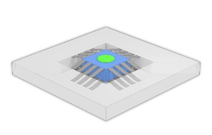
NIST researchers are working on perfecting a silicon-based optomechanical accelerometer.
That is why researchers at the National Institute of Standards and Technology (NIST) have developed and are testing a novel silicon-based optomechanical accelerometer less than 1 mm thick (in optomechanical devices, light interacts with mechanical components -- usually on the scale of micrometers or smaller -- for some function or effect). It is designed to deliver measurements directly traceable to the SI (Système international d'unités -- the International System of Units) with uncertainties better than one part in 1,000 -- "as good as any laboratory acceleration device in the world," says project scientist Thomas LeBrun of NIST's Physical Measurement Laboratory.
Accelerometers typically function by measuring the change in position of a free-mounted "proof mass," typically a solid block, relative to some fixed point of reference inside the device. If the system is at rest or moving at constant velocity, the distance between the proof mass and the fixed reference point will not change. Analogously, the distance between the dashboard and a front-seat passenger in a car doesn't change while driving at a steady 60 mph.
But if the accelerometer speeds up or slows down, the separation between the proof mass and the reference point either increases or decreases. Similarly, when the car's driver suddenly hits the brakes, the passenger is shifted forward toward the dashboard, putting pressure on the seat belt.
Accelerometers convert that kind of displacement to a measurable signal of some sort. For example, movement of the proof mass might compress a piezoelectric material, generating a current, or it might stretch a sheet of insulator so that its electrical resistance increases. The devices have now shrunk to the size at which they can be fabricated using technology in widespread use to make microelectromechanical devices (MEMS) and microelectronics.
The new NIST device uses infrared (IR) laser light to measure the change in distance between two facing, highly reflective surfaces separated by a very small empty space in the center. (See animation.) On one side is the proof mass, a square slab of silicon with a flat mirror coating on its inner face, suspended within the cavity by tiny flexible beams on the top and bottom edges that act as springs, allowing the mass to move relative to its surroundings when the device experiences an acceleration.
On the other side of the empty space is a fixed hemispherical concave mirror, facing inward toward the proof mass. This kind of facing-mirror arrangement constitutes what is called a Fabry-Perot cavity.*
When IR light is initially sent into the cavity, nearly all of it is reflected -- except for one particular wavelength that is exactly the right size to reflect back and forth between the two mirrored surfaces and resonate, forming a standing wave and increasing in intensity by a factor of a thousand so that enough light is transmitted by the cavity to be detected. The wavelength of the resonant wave is determined by the distance between the two mirrors, much as the pitch of a trombone note depends on how far the slide is extended or retracted.
"The optical method provides much better sensitivity and lower uncertainties," says LeBrun, "because, among other reasons, we can control and measure the wavelength of light to very high accuracy."
VIDEO: This animation demonstrates the operating principles of a new accelerometer. This optomechanical accelerometer consists of two silicon chips. The first chip has a proof mass suspended by a set of silicon beams, which allows the proof mass to move vertically. The top of the mass has a mirrored coating. The second chip has an inset hemispherical mirror. Together the mass and hemisphere mirrors form an optical cavity. Infrared laser light is directed into the device. Most frequencies are reflected entirely. However, light matching the resonant frequency builds up inside the cavity, increasing in intensity, until the intensity of the light transmitted by the cavity matches the input. Light transmitted by the cavity can be detected on the other side. When the device accelerates, the length of the cavity changes, shifting the resonant frequency. By continuously matching the laser to the resonant frequency of the cavity, researchers can determine the acceleration of the device.
MEMS-based Fabry-Perot configurations have been tried before for small accelerometers, typically with the mirrors mounted in two parallel planes facing each other. "That's challenging," LeBrun says, "because it's very difficult to make that kind of design extremely precise. If one of the mirrors does not focus the light into the cavity, the light is lost much more rapidly, reducing the precision. In our design, high-quality mirrors keep the light in the cavity, while the proof mass -- suspended by flexible beams about one-fifth the width of a human hair -- is designed to act as an ideal spring. That maximizes stability and eliminates potential rocking motion, allowing for higher-sensitivity measurements."
Except for mirror coatings and the silicon nitride beams holding the proof mass, all of the accelerometer components are made of silicon, which has several advantages. One is the ready availability of proven technologies for shaping and processing silicon to high tolerances in small dimensions.
That is important for the NIST design, in which the fixed hemispherical mirror is about 300 micrometers (µm) deep, 500 µm wide, and has a surface smoothness that varies by no more than 1 nanometer. (The accelerometers LeBrun and colleagues used for experiments were fabricated at NIST's Center for Nanoscale Science and Technology.) In addition, silicon provides very good thermal stability and is transparent to IR light.
"The distinguishing characteristic of this device is that it is optomechanical rather than electromechanical," says LeBrun. "Because accelerometers are electromechanical devices, acceleration (in meters per second squared -- a unit with no intrinsic electrical nature) is read out and calibrated in terms of electrical quantities such as volts."
"Our devices, because they incorporate a microinterferometer, can be directly read out in terms of optical wavelength. Omitting scaling factors for voltage or charge allows very accurate measurement of acceleration directly traceable to the meter," says LeBrun.
The laser light source is placed behind the proof mass on one side of the device; on the other side, behind the hemispherical mirror, is a light sensor/detector. The laser is "tunable," capable of producing a range of IR wavelengths. During acceleration, as the distance between the proof mass and the hemispherical mirror changes, the laser wavelength tracks the resonant wavelength of the cavity. As a result, the laser gives a direct, fast, and highly accurate readout of the proof-mass motion.
The measurements must be extremely precise. "Changing the cavity length by less than 1 nm completely extinguishes the optical resonance," says project scientist Jason Gorman.
Because the sensor operates using a laser with a well-characterized wavelength, it can be intrinsically self-calibrating. And because the components and manufacturing methods are the same size as those routinely used in microelectronics or MEMS fabrication, the eventual production cost of a complete unit should be low. But before then, the NIST scientists will have to overcome a number of obstacles.
"One is the demanding time scale involved," Gorman says. "As the cavity dimension changes, the tunable laser will have no more than about 100 microseconds to scan the wavelength over a wide range so that it tracks the cavity motion. Finding an inexpensive laser with those capabilities is another challenge. So is making a robust optical fiber connection to a device that is vibrating at 1,000 cycles per second -- and eventually perhaps 10 times faster."
"We fully expect this optical microcavity technology to result in field-deployable accelerometers with intrinsic accuracy probably 10 times better than currently possible," says John Kramar, the leader of the Nanoscale Metrology Group. "But what is even more exciting is the wide range of other types of sensors and applications that this technology could dramatically improve, including ultrasound, microphones, altimeters, pressure sensors, gyroscopes, and geophysical exploration."
* Fabry-Perot cavities are used to control or measure the wavelength of light. The spacing between the mirrors determines which wavelengths cancel out, and which reinforce each other and form a standing wave in the cavity. Changing the cavity spacing changes the resonant wavelength.
Source: NIST
Published April 2017
Rate this article
View our terms of use and privacy policy